

Front notched joint
Both members have a 160 × 240 mm cross-section. The inclined member meets the beam at 30°. Notch depth is 40 mm; the timber length from the bearing face to the beam end is 400 mm.
Explore the joint in 3D.
Where is it used?
For inclined compression members in timber trusses and roof frames, such as a rafter or strut bearing into a horizontal tie beam. The notch transfers compression directly through timber contact. [1, 2]
The front face carries bearing force; the timber ahead of the notch resists its horizontal component. The connection must match the structural model of the whole frame. [2]
Essential requirements
- Provide accurate, fully contacting bearing faces; cracks and gaps change the actual force transfer.
- Check compression at an angle to grain, shear in the timber ahead of the notch and the reduced beam section. [1, 2]
- The notch alone does not provide a verified tension or uplift connection. Design position restraint, lateral stability and erection conditions.
Front notch geometry
- Horizontal beam b × h
- 160 × 240 mm
- Inclined member b × h
- 160 × 240 mm
- Member angle α
- 30°
- Vertical notch depth tᵥ
- 40 mm
- End shear length lᵥ
- 400 mm
- Remaining beam depth
- 200 mm
- Horizontal bearing projection
- 480 mm
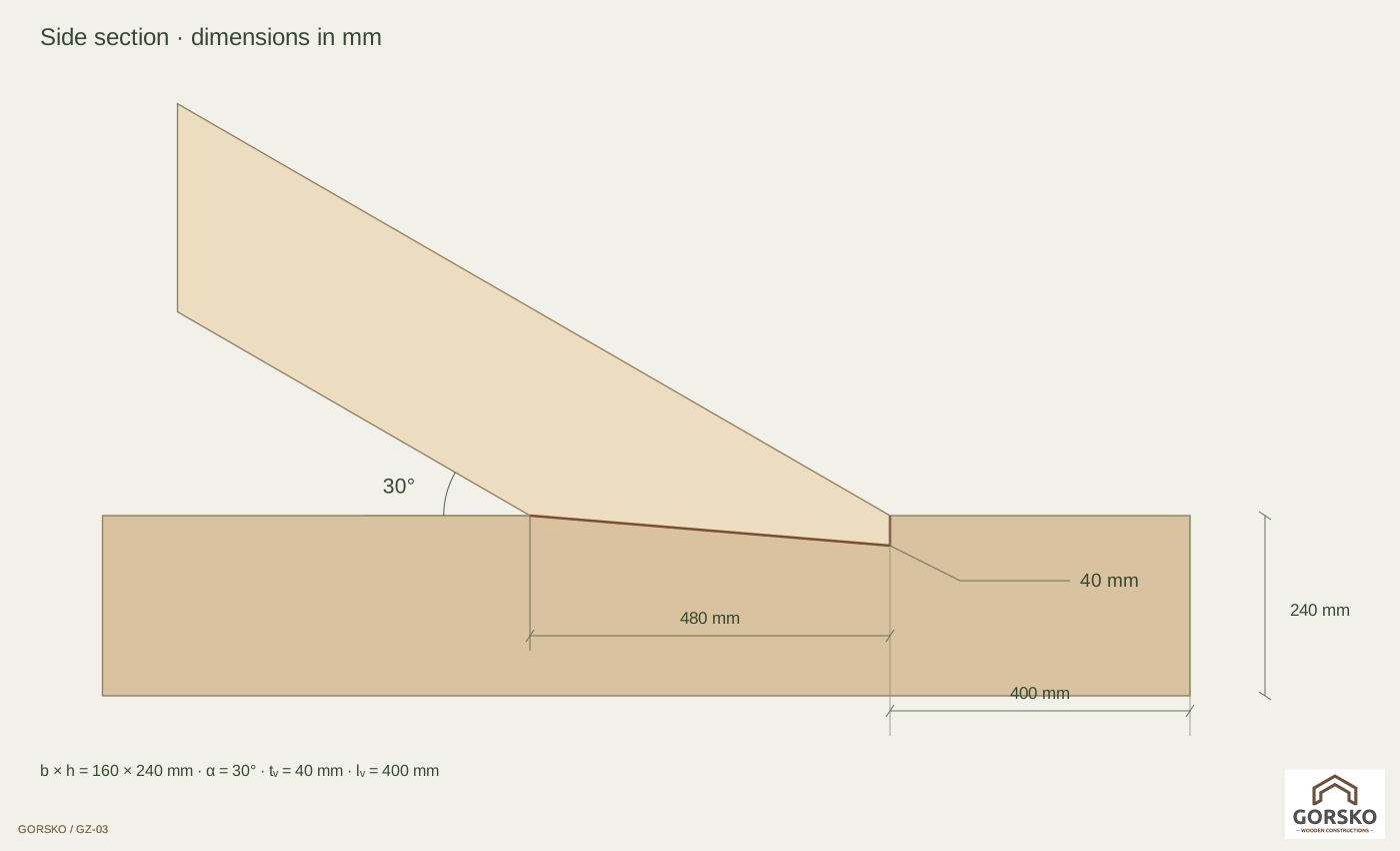
Shape approved by GORSKO: a long shallow bearing surface and a short vertical front step. With 160 × 240 mm sections at 30°, the horizontal bearing projection is 480 mm. Step depth is 40 mm; step-to-beam-end distance is 400 mm.
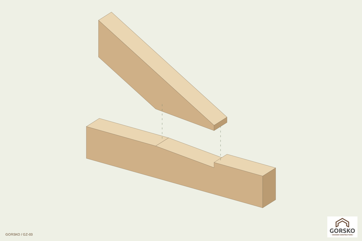
Align the members across their width. Lower the inclined member into the notch until full bearing is achieved; check the front face and seat. Install the specified restraints afterwards. The animation shows timber assembly and is not a lifting plan.
Design starting points
For α = 30° and h = 240 mm, the literature depth limit h/4 is 60 mm. The illustrated 40 mm is below this geometric limit; this does not prove load capacity. [1, 2]
- Determine design axial compression NEd and its components, timber strength class, moisture, load duration and safety factors.
- Check compression on the actual contact surfaces, grain direction and distribution of contact forces. This shape does not use a bisector front face; the structural engineer must verify the calculation model.
- Check shear ahead of the notch. Starting point: HEd = NEd · cos 30°; determine effective shear length and width under the adopted design method. [2]
- Check the remaining 200 mm depth, axial force with bending, eccentricity, splitting, stability and any required restraints.
The physical end distance is 400 mm. The cited method limits effective shear length to 8 · tᵥ = 320 mm. The extra 80 mm therefore does not automatically increase the design shear area. The cited construction minimum is 200 mm. [1, 2]
No capacity has been calculated: loads, timber grade and project conditions are missing. These are literature-based starting points. The structural engineer must check the current Eurocode 5, applicable National Annex and suitability of the selected method.
Technical references and scope
- BUBIZA: Bemessung und Konstruktion im Holzbau, 2023, Versätze 4-12 ↗
- D.I.E. Statik Software: Stirnversatz (DIN 1052:2004-08) ↗
[1] BUBIZA 2023, Versätze 4-12: geometry, bearing and end shear checks.
[2] D.I.E. based on the older DIN 1052:2004-08 explains basic checks. Its bisector configuration differs from the approved GORSKO shape. Equations must not be transferred without verifying the model.
The PDF uses your selected language. Free download with no catalogue registration.