+386 30 427 414info@gorskoabbund.com
← Back to catalogue
GZ-02 / Post-to-purlin connection

Post tenon

Post 160 × 160 mm and purlin 160 × 240 mm. Tenon: 100 mm overall length along the purlin, 60 mm across it, 60 mm engagement and rounded ends R30.

Save as PDF ↓Free · no form
Geometry proposal · capacity not verifiedRevision 06 / 2026-10-18
01 / Interactive model

Explore the joint in 3D.

Assembled connection
Drag to rotate · Wheel or pinch to zoom · Keyboard: arrows, + and −
GORSKO · Technical illustration
Post160 × 160 mm
Purlin b × h160 × 240 mm
Tenon L × b × d100 × 60 × 60 mm
Rounded-end radiusR30
02 / Application and requirements

Where is it used?

Connection of posts to intermediate or ridge purlins above. The tenon guides assembly and locates the members; post shoulders provide bearing for the vertical support force. [1]

The intended compression path is through the purlin bearing on the shoulders, not through the tenon tip. Avoid water accumulation in the mortise. [1]

Key requirements

  • Machine shoulders in one plane. The mortise bottom must not prevent full shoulder contact. [1]
  • Check remaining timber, splitting and force direction at the purlin end; 50 mm is a GORSKO execution recommendation.
  • The tenon alone is not verified restraint against wind uplift, withdrawal or global lateral instability. The designer specifies any additional fixings.
03 / Geometry

Tenon, mortise and bearing dimensions.

Post
160 × 160 mm
Purlin b × h
160 × 240 mm
Tenon L × b × d
100 × 60 × 60 mm
Rounded-end radius
R30
Setbacks: centred / offset
30 / 30 mm · 50 / 10 mm
Minimum width / maximum length
40 mm / 120 mm
Section along the purlin
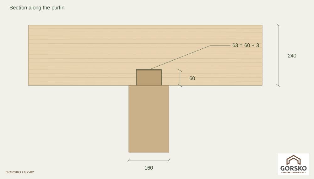
The tenon engages 60 mm into the purlin. The mortise should be a few millimetres deeper to allow shoulder bearing [1]; this model uses an illustrative 63 mm (3 mm bottom clearance). Timber remaining above the pocket is 177 mm. Specify side fit and final depth in the fabrication drawing.
Exploded assembly · assembly principle

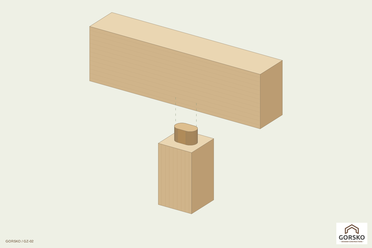
Align the purlin above the tenon and lower it vertically until it bears fully on the shoulders. The tenon must not wedge into the mortise. Install any additional hardware specified for the project.

Two variants, the same bearing principle.

Centred variant

Plan of post head: Centred variant

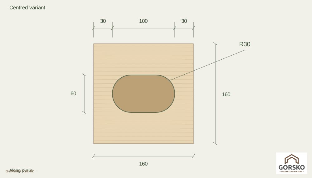
The tenon is centred on the post: 30 + 100 + 30 = 160 mm along the purlin. Across the purlin, each shoulder is 50 mm wide.

Offset at purlin end

Plan of post head: Offset at purlin end

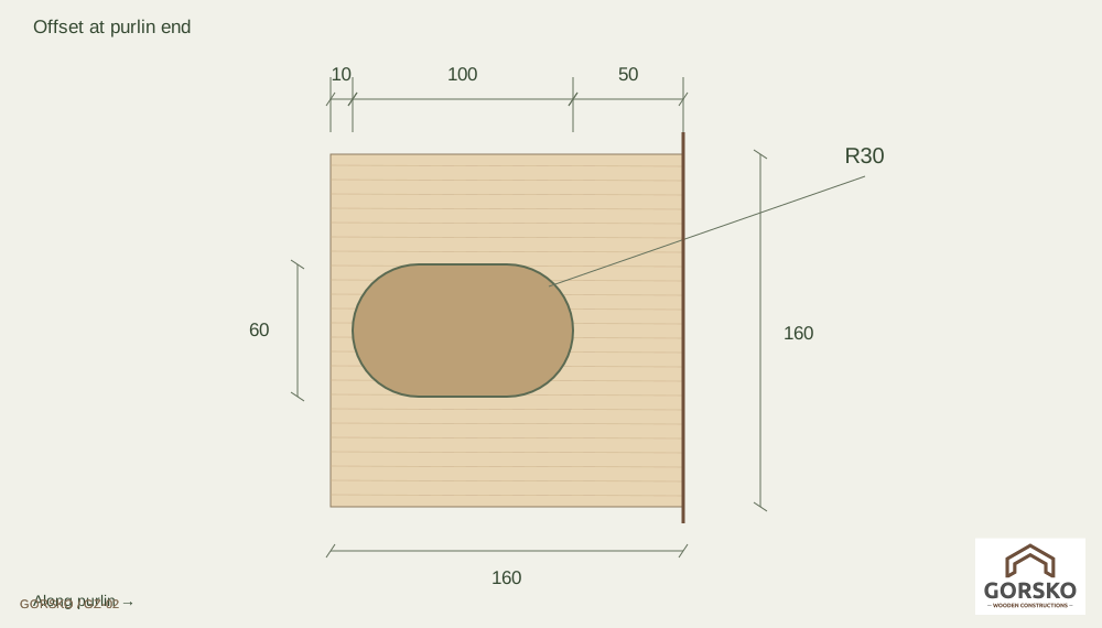
Where the purlin ends flush with the post edge, move the tenon 20 mm towards the purlin interior. From the purlin end: 50 mm setback, 100 mm tenon and 10 mm to the opposite post edge.

GORSKO recommends the 50 mm end setback to retain more timber between the mortise and the purlin end and reduce breakout risk during assembly or service. It is not a universally verified structural edge distance.

Adjustments and machining limits

Width may be reduced below 60 mm, but GORSKO specifies a minimum 40 mm for the Ø40 cutter. Length may be up to 120 mm. For an obround profile R = width/2: a 40 mm width requires R20, not R30. Length includes both rounded ends.

Dimensions interact. A 120 mm centred tenon gives 20 + 120 + 20 mm; the 50 mm end setback cannot fit a 160 mm post (50 + 120 > 160). Change the tenon length, detail or post section.

04 / Design

What must the calculation cover?

Geometric shoulder area for a 100 × 60 mm, R30 tenon is approximately 20,373 mm²: 160² − [60 × (100 − 60) + π × 30²]. This is not the code-effective bearing area or a capacity.

  1. Compression perpendicular to grain in the purlin and parallel to grain in the post; determine actual and code-effective bearing areas for the project.
  2. Post capacity and stability, purlin bending and shear, and section reduction by the mortise.
  3. Lateral forces, splitting near the pocket, purlin end distance, uplift and any additional anchorage.
  4. Timber grade and moisture, load duration, tolerances, timber protection and fire requirements.
Without loads, spans, supports, timber and steel grades and service conditions, capacity and hardware adequacy cannot be confirmed. Use the applicable Eurocode 5 edition and national annex, together with relevant steel component standards. This illustration is not a verified structural calculation or fabrication drawing.

Technical references and scope

  1. BUBIZA: Holz-Holz-Verbindungen, pp. 51–59 ↗

[1] BUBIZA: vertical tenons, pp. 51–59. Based on the older DIN 1052, it explains positioning, bottom clearance and reduced bearing area; it is not a current normative basis.

The 160/160 and 160/240 sections, 100/60/60 tenon, 50 mm recommendation and 40/120 mm machining limits are GORSKO inputs, not dimensions structurally validated by this source.

Save as PDF ↓

The PDF uses your selected language. Free download with no catalogue registration.