+386 30 427 414info@gorskoabbund.com
← Back to catalogue
GZ-01 / Longitudinal timber joint

Gerber joint

Geometry, function and assembly in one place. The example uses a 200 × 400 mm section and a 400 mm long joint.

Save as PDF ↓Free · no form
Geometry proposal · capacity not verifiedRevision 06 / 2026-10-18
01 / Interactive model

Explore the joint in 3D.

Assembled joint
Drag to rotate · Wheel or pinch to zoom · Keyboard: arrows, + and −
GORSKO · Technical illustration
Section b × h200 × 400mm
Joint length400mm
Top / bottom notch100 / 100mm
Holes in timber2 × Ø22mm
02 / Application and requirements

Where is it used?

The Gerber joint is used for hinged splicing of timber beams away from a direct support, particularly in Gerber beam and purlin systems. It can also be used in beam repairs. [1, 3]

It allows shorter members to be used. The joint position follows the structural model, normally at the intended zero-moment location. There is no universal offset from a support for every system and loading pattern. [1]

Key application requirements

  • Orient the upper and lower members correctly in relation to supports and shear direction; incorrect arrangement increases the risk of splitting. [1]
  • Shear transfer involves bolts and large washers or bearing plates. Possible load reversal must also be considered. [1]
  • Accurately machine mating faces; protect the joint from moisture and provide access for installing and inspecting the hardware.
03 / Geometry

Geometry and hardware, clearly separated.

Timber machining

Section b × h
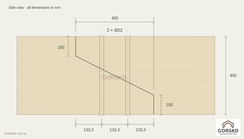
200 × 400 mm
Joint length
400 mm
Top / bottom notch
100 / 100 mm
Holes in timber
2 × Ø22 mm
Axes from start of joint
133,3 / 266,7 mm
Axis across width
100 mm
Contact plane angle
26,6°
Side view · all dimensions in mm

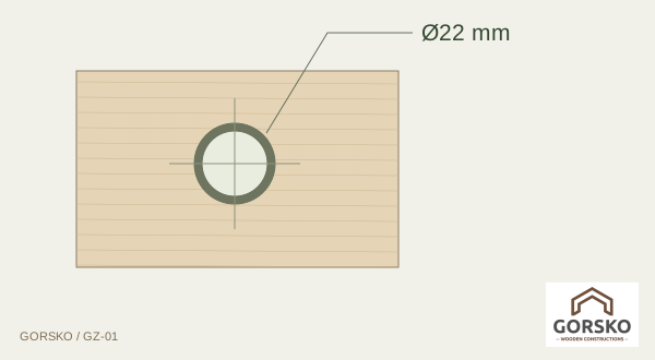
Ø22 mm hole

Ø22 mm hole

Two vertical through-holes in the assembled joint. Their axes are at the thirds of the joint length and centred across the member width.

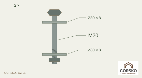
M20 bolt with washers and nut

Diagram of one set · not to scale

Each of the two holes is shown with one M20 bolt, two large washers and one nut. Bolt length and steel grade must be specified by the designer.

The Ø22 mm hole and M20 bolt are separate specifications. The illustrated 2 mm diameter clearance must be checked for the selected bolt type and loading.
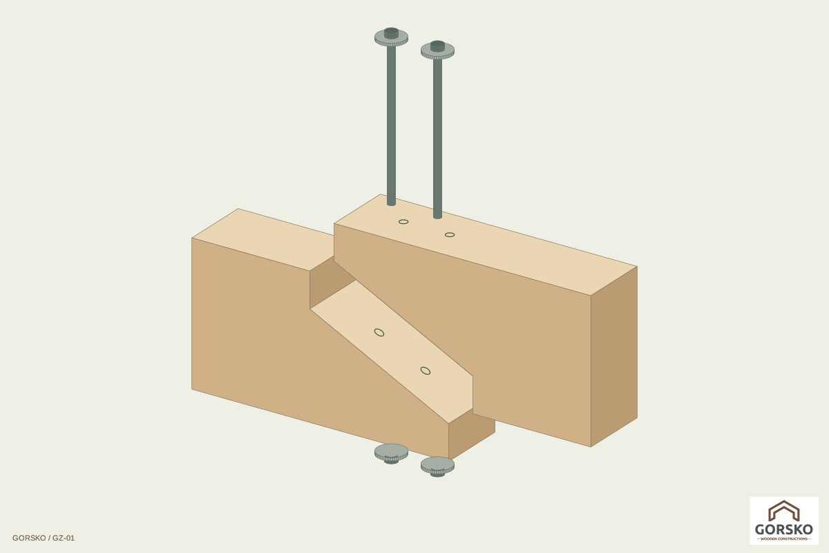
Exploded assembly · assembly principle
04 / Design

A starting point for project-specific design.

The 200 × 400 mm section, 400 mm length and 0.25h = 100 mm notches are the supplied initial geometry. The inclined plane joins heights of 300 and 100 mm, giving an angle of 26.6°. These are not universal recommended proportions for all loads.

  1. Structural system, hinge position, design shear, any axial forces and reversal of loading.
  2. Timber shear, local bending, net sections and splitting at notches and holes.
  3. Bolt tension, compression perpendicular to grain beneath washers, and washer or plate bending and effective bearing area.
  4. Distances, tolerances, timber and steel grades, load duration, moisture, corrosion protection and fire requirements.
Without loads, spans, supports, timber and steel grades and service conditions, capacity and hardware adequacy cannot be confirmed. Use the applicable Eurocode 5 edition and national annex, together with relevant steel component standards. This illustration is not a verified structural calculation or fabrication drawing.
05 / Hardware

Illustrated hardware

Initial assembly for detail development, not an approved purchasing list. Quantities apply to the complete joint.

ComponentQuantitySizeVerify for the project
Bolts2M20 Verify for the project
Washers4Ø80 × 8 mm Verify for the project
Nuts2M20 Verify for the project

Ø80 × 8 mm washers are an illustrative proposal. The 8 mm thickness has not been verified by calculation. Bolt length, grades, standards and protection are to be specified after checking.

06 / References

Technical references and scope

  1. BUBIZA: Holz-Holz-Verbindungen, pp. 16–21 ↗
  2. Harzer Software: Gerber-Gelenk Holz, example calculation ↗
  3. Material-Archiv / ETH Material Hub: Gerberstoss ↗

Reference [1] explains use, orientation and checks for timber, washers and bolts. It is based on the older DIN 1052 and is not a current normative basis.

Example [2] concerns a different joint variant. Its capacity and selected hardware do not apply to this detail. Reference [3] describes Gerber joint applications.

Save as PDF ↓